Tuesday 21 October 2014

The Sith fighter

Today I began working on my next Star Wars ship model, The Sith fighter. The images I used to aid in creating this model were:

 The Base/Cockpit

I began by creating the base/cockpit of the model which did not consist of any advanced techniques. The front of the model is a cylinder with reduced axis sub divisions which can be applied through the attribute editor. I then proceeded to use the move tool to bring the front of the cylinder forward and then used the scale tool to make the cylinder become progressively thinner.

 The engine of the ship also consists of another cylinder. To manipulate its shape to create thin and thick parts of the shape, I used the extrude tool. The steps I took were:

1. Select all the faces on the back of the cylinder.
2. Use the "extrude face" tool to extrude the faces.
3. Use the scale tool and reduce the size of the faces selected.
4. Extrude the faces again (skip if making progressively thinner/thicker) and use the move tool to stretch them backwards.
5. Repeat when needed.


The Wings

I began creating the wing by creating the connections between the base and the wing. The first part consisted of two cubes. The first cube included the use of the "Difference" tool which can be found under the Mesh drop down bar in the Boolean tools. This allowed me to manipulate the cube by putting another cube inside the shape where I wanted it to be cut as shown in the screenshot below.

After I had completed one side of the wings I used the group feature (CTRL + G) and named the group "right wing." I then duplicated the right wing group and reversed the scale of the Z axis from 1 to -1. This gave me an issue where all the faces began inside out (appeared black) which I was able to fix by reversing the normals. (Normals > Reverse.)

The result was this:

 Now that I finished designing my Sith fighter, I made sure that all the groups I created during the creation of the model were named and organised properly by opening the Outliner from the Window drop down. I also began preparing the texture all three of the star wars models I had designed.


Wednesday 15 October 2014

Working on the X Wing ship

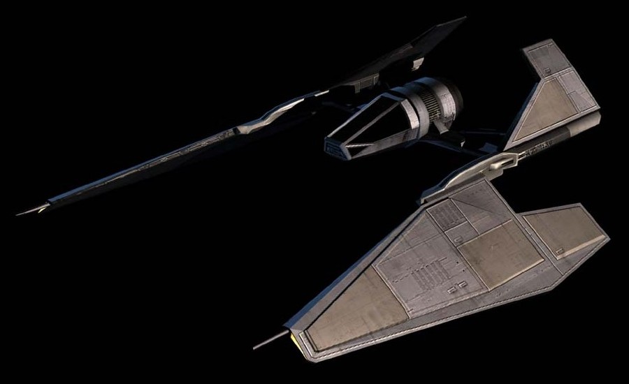
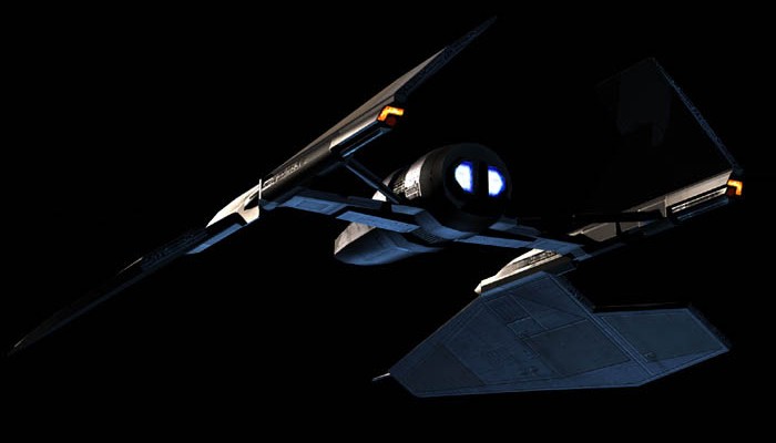
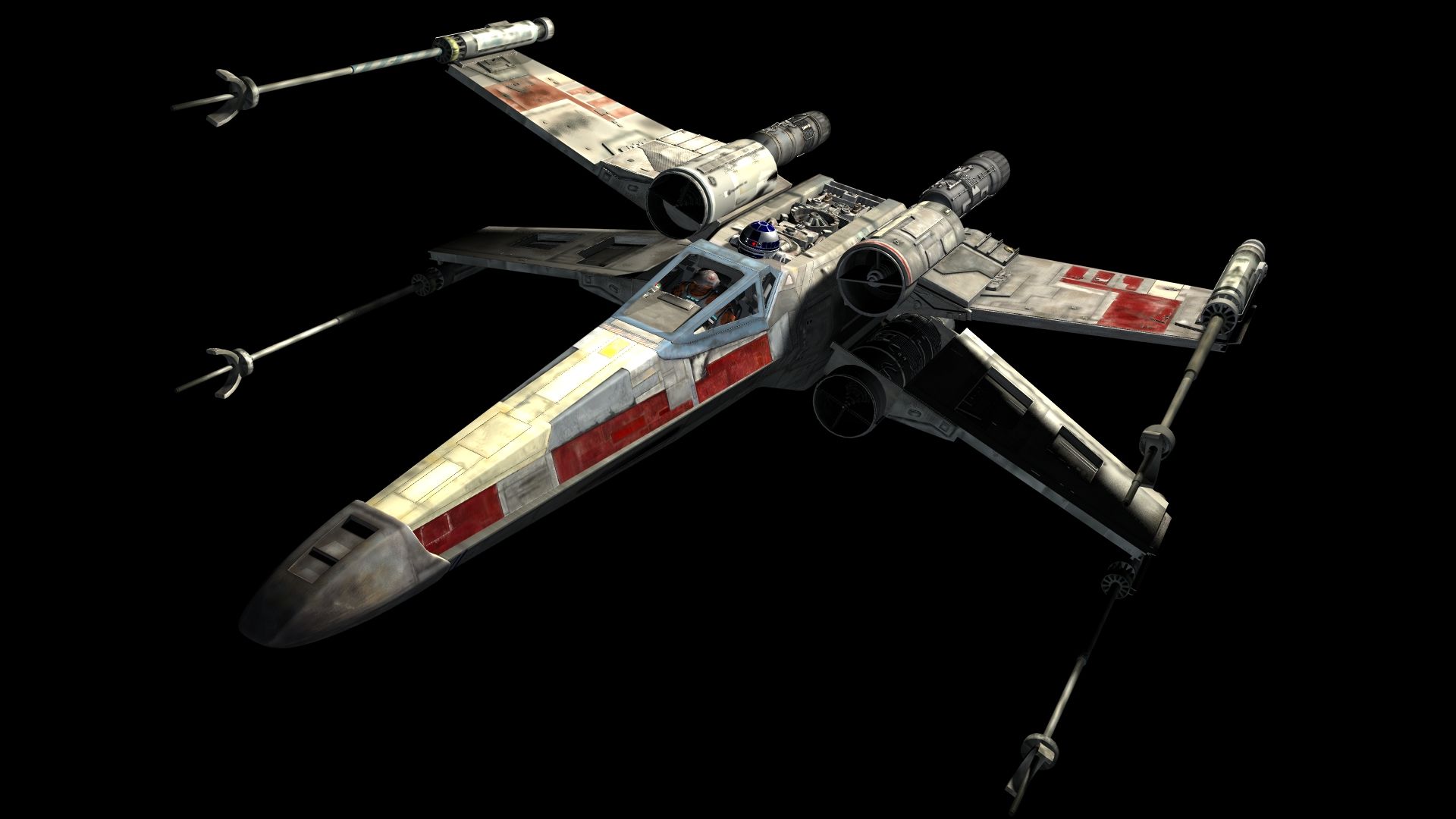
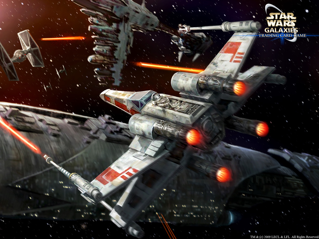
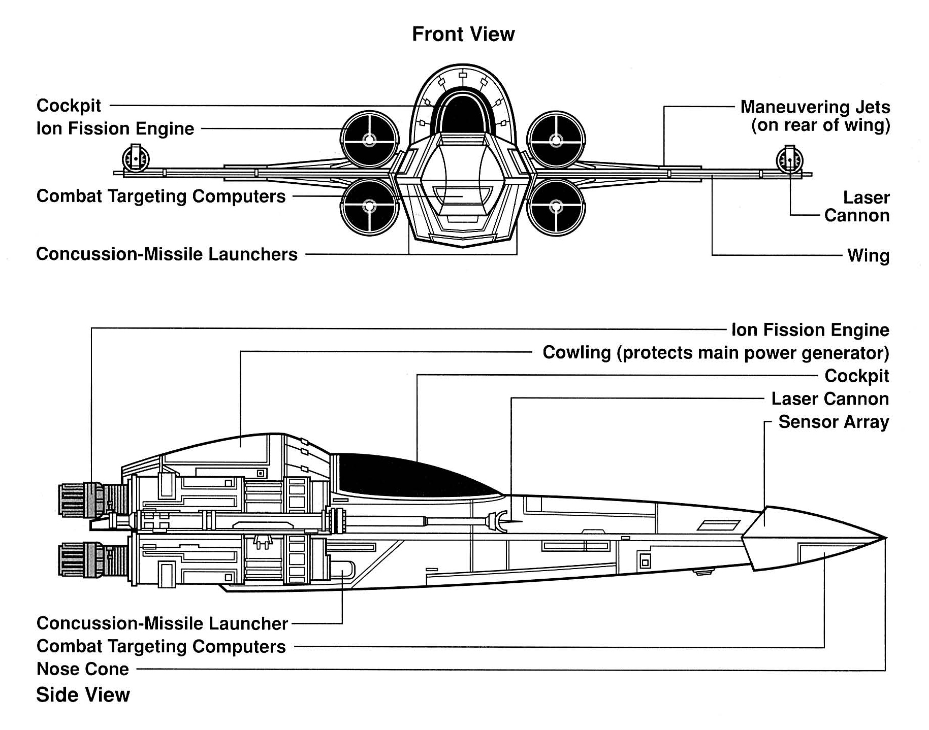
Today I began working on my second Star Wars ship, the X-Wing. Compared to my previous ship, the Z-95 HeadHunter, there were a lot more 3D images of the ship I could use to give me a good accurate guidance for modelling this ship. The images I am using for guidance are:


I began by creating a cylinder and reducing its subdivision axis to 6 to give it the same shape body as the X-Wing.
To create the nose of the X-Wing I selected the top and bottom edges of the front of the cylinder and used the scale tool to close them in together. I also selected the edges on the sides and used the move tool to make the cylinder more pointy as seen below.
To create the rest of the body, I selected the faces from the back of the cylinder and used the extrude face tool to extend the body and used the scale tool so that it gradually became bigger and thicker. To change the falloff point I used the soft select tool and modified the fallout radius as well as the fallout curve.

I created the cockpit by using the edge loop tool to create more edges. By using the move tool on the newly created edges, I was able to create the "slope" on top of the base to give the shape of a cockpit. 

To create the laser cannon of the ship, I created a cylinder. To manipulate the shape of it, I used the edge loop tool as well as the extrude tool to create the thin and thick parts of the shape. I found this was much more effective than what I did with the Z95 HeadHunter which was just creating multiple cylinders and resizing them.
To create the curled "C" shape of the laser cannon, I used the bend tool to bend a cube into a "C" shape. To do this I first had to create a cube and set its height subdivisions to 6. I then changed to the animation menus. From there I went to Create Deformers > Nonlinear > Bend. In the attribute editor, I had to modify the curvature till I got the result I wanted.

After I added some detail onto the wings, I ran into some issues with the three other wings after duplicating them and getting them into the correct rotation after being placed in the different positions. 

One way I found which helped me overcome my problem when flipping the wing is to set its scale to a negative value. The problem I encountered with this however is that all the faces could be flipped inside out which would cause the wing to turn black as shown in the image below.

To overcome this I found that if you highlight all the faces of the wing and go to Normals > Reverse in the menu, it flipped the faces so they faced the right way.
After creating the four engines and adding in some extra details, I had completed modelling the ship. 


Sunday 12 October 2014

Z95 Headhunter continued and finished

The Cockpit

I began working on the Z95 Headhunter's cockpit. I did this by adding a couple of edge loops to the base of the ship. I then rotated two of the new edges created both diagonally to make the cockpit look thin like the actual Z95. I then raised the back edge to give the "ramped" look of the cockpit.

The rest of the ship

As you can see in the below screenshot, I used the edge loop tool multiple times. This was so that I could get the smoothest curve when I increased the height of the Cowling (see Z9 headhunter schematics in previous blog post.) Although this was costly on polygon count, I wanted my ship to look as accurate as possible.


Saturday 11 October 2014

Designing the Z-95 Headhunter continued...

In my last blog post I explained how I created the base, wings and laser cannon.

Today I worked on creating the engines and manipulating the base of the ship to create a cockpit.

The Engines

My engine consisted of multiple pipes overlapping each other. Although I found this used more polygons than just using one pipe and using the edge loop tool to manipulate the shape of the pipe , I found this did not look as accurate as using multiple pipes. The amount of extra polygons was also not too expensive than using the edge loop tool.

Creating the main pipe
Creating more pipes
The front of the engine
 For the front of the engine, I used the scale tool to widen a cube. I then sub divided width by 7. I then selected the top middle face and used the move tool to increase its height.

To create the curved pipe as you can see in the second screenshot of the engine, I created a pipe as normal and then selected the front faces and used the scale tool so it became progressively smaller.


I then extruded the faces on the opposite side.

With the engine finished, I proceeded to copy and paste the engine into three other locations.

Engine now completed


Friday 10 October 2014

Use of booleans, sub divisions and the align tool

Today I worked on the Week 2 modelling basics. This included the use of booleans, sub divisions and the align tool and grouping.

Booleans

I found that the use of booleans could be incredibly useful for designing the rest of my Star Wars models however I did notice one issue. Depending on the shape used to cut through an object, it would potentially cause a drastic increase in the polycount of the scene. I found this to be a problem when using a sphere with the boolean interceptor on a cube.

Whilst the tool can be useful for creating shapes which would be hard to accomplish with other methods, I found a decent but not perfect workaround. If you are using a sphere, you can simply reduce its subdivisions amount before using it, as a way of reducing the polycount. The only issue here is that it could lower the detail of the object after it has been used.

Align Tool

I found the align tool to be extremely useful and anticipate it will greatly aid me later on when designing my other Star Wars ships. It was extremely helpful in my last practical lesson when trying a roof perfectly on top of my house as you can see in the screenshot below.

Alignment Task

Using the Align Objects Option window in Maya, I was able to stack four objects all directly on top of each other. I began by creating the four objects (cube, sphere, cylinder and cone) and then highlighting the objects and opening the align objects options window. I then ticked all the "Align in" boxes so that they would all be aligned in the X, Y and Z axis using align mode min.

Afterwards I un-ticked the X and Z axis and set the align mode to "stack" so that all the objects would stack along the Y axis. The results are shown below:


Merge Vertex Tool


A great tool I discovered on my own recently is the Merge Vertex Tool. Sometimes when using the edge loop tool and deleting edges created from the tool which I don't need, I can sometimes be left with other split edges around the object. To counter this issue, I found the merge vertex tool useful in being able to merge the edges back into 1 single edge like it previously was before the deletion of another edge.

Thursday 9 October 2014

Designing my first Star Wars ship. The Z95 Headhunter.

The first Star Wars ship I am going to design in Maya 2015 is the Z-95 Headhunter. I was able to find some good sample pictures and schematics from the Star Wars wikia page. The image I am currently using to design the Z95 Headhunter is the image below.

I am also using two other images to provide angles which the above image does not show.

Third image from http://www.maje3d.com.

The schematics are useful because it allows me to get an idea of what my model should roughly look like from a front view and side view. The third image allows me to get a good view of what my model should look like from a back view. 

The Nose

I started by creating the "nose" of the model by creating a cylinder and reducing its subdivision axis to 6. I also increased the subdivision height to 5. This gave me the amount of sides needed. Using the scale tool I was able to flatten the cylinder to create the shape I wanted. Using the move tool I then stretched the edges at the front of the cylinder to create the pointy noise effect as you can clearly see in the first example image at the top of the post. The outcome is shown below.


The Base

To create the base of the ship I created another cylinder and lowered its subdivision axis to 6. As you can see from the images of the Z95 Headhunter, the base of the ship starts off thin from the front and progressively gets thicker. To manipulate the shape to the way I wanted in Maya, I used the Extrude Tool from the Edit Mesh bar and extruded the face of the cylinder. I then used the scale tool so that I could make the ship progressively get thicker and accurately recreate the shape I wanted.

The Wings


To create both wings I started off by using the cube tool and resizing it to a flat rectangular shape.


To add more detail to the wing I added in two more cubes and moved the top edges downwards to make it ramp shaped.


To create the laser cannon on the side of the wing, I created multiple cylinders and scaled them to accurately recreate what the Z95 Headhunter's laser cannon looked like.

A new tool I discovered after researching which was to create the curved shape I needed to finish the laser cannon is the "Bend Tool." To use the Bend Tool I had to first create a cube and set its sub division to 10. I then switched to the animation menu set and from the deform menu, I selected the bend tool. Once on the bend attribute editor, I could change how much I wanted the cube to bend by simply changing the curvature.

Before:
After:

Now that the left wing is complete, I used the keyboard shortcut "CTRL + G" to group the wing together.

This allowed me to paste a new wing as a group so that it could be easily rescaled so that the right wing could mirror the left wing.


Wednesday 8 October 2014

Low polygon house and creating a castle!

In my first lesson, I attempted to create the low polygon house. During the lesson I learned about a few helpful features in Maya which I will definitely use in the feature. This included the "extrude tool" which can be used to extrude faces and edges. This allows me to extend the object and manipulate its shape by adding a new face/edge to it.

The sub division tool is also a new useful feature I have learned to use in Maya. It is able to subdivide an object so that it has more faces. I found this would be useful when needing to keep halving an object evenly and it will be far more accurate than using the edge loop tool.

The edge loop tool is another handy feature I learned about which allows me to create new edges in an object.

Below is the screenshot of the house I created:


Unfortunately I was not able to complete the low polygon house. I struggled to use the edge loop tool on the roof of the house. The edge loop tool refused to create new edges and I was not able to replicate the images in the guide which prevented me from finishing the roof. I do not understand why this was happening however I wish to resolve this issue in the future.

Creating the Castle

My second task in the lesson was to create a castle. It had to contain four walls with raised battlements and ramparts, arched entrance, a watch tower on each corner and an inner keep with an entrance. It could also contain a moat and drawbridge.

I began by creating one wall with the watch towers on either side. This allowed me to duplicate these walls later and easily position them so I could have 4 walls and 4 watch towers. To create the wall I used the extrude face tool to give the wall a "castle look."  To create the watch dogs I used one cylinder and one cone. I used the extrude face tool to give the castle brick look on the cylinder as well as using the extrude face tool to extend the cylinder and put the cone on top.

Afterwards I pasted the walls and watch towers appropriately until I had 4 walls and watch towers. I began to work on the arched entrance. To create the two ramparts on either side of the gate, I used the watch tower design but deleted the cone and extruded top part of the cylinder. To create the gate I used a sphere and cube, used the boolean tool "union" to merge them and the used the boolean tool "intercept" to create a arched gate shaped hole inside the wall.

I began creating the drawbridge. This consisted of a cube with extruded faces. Nothing special was used to create this. To create the water surrounding the castle I created a thin cube and from the colour menu, I used the Apply Colour tool and applied a blue colour. I would have used a plane instead of a cube however I was getting odd issues with the plane properly displaying.

To finalise, I populated the castle by adding some small buildings which consisted of cubes for the building itself and a cone for the roof.