Sunday 7 December 2014

Some helpful techniques

 Hiding and Unhiding

During the process of animating I can come across a really useful tool in Maya which is the "Hide" tool. The hide tool allows me to make objects "hide" (go invisible) and they can be unhidden at any frame. This has been useful for creating bullets since once I am done using a bullet I can hide the bullet and therefore the bullet is no longer taking up any space and nor is it being rendered. The hide feature can be used by pressing CTRL + H on an object when on the correct frame. The object can also be unhidden using SHIFT + H.

Glow

Whilst creating my animation, I was always looking for a way to add a flare to the engine to give a better impression of the ships flying rather than just floating quickly in space. I attempted to use point lights and spot lights, however this did not give me the results I wanted and I found it difficult to get the right light settings possible. For example I would find that using lights, lit up other parts of the ship or would affect the lighting on the sky box which did not look right. I came to the conclusion that the best choice was to use the glow feature. This can be found in the "special effects" section in the attribute window on a material.

Here are some examples of the results I got from using the glow special effect. As you can see the glow effect gives a "powerful" shine effect which helps reflect the flare of the engine and gives a better impression of the ships flying.

The only downside I found to using the glow effect is that I now am required to render using "Maya Software" rather than "Maya Hardware." I have found that Maya Software is slower for rendering however the results make it worth the time.


Friday 5 December 2014

SWOT Analysis

I have developed a SWOT Analysis to demonstrate the strengths, weaknesses, threats and opportunities of the experience of creating my animation.
 
Strengths
30 Second Limit – Due to the animation only needing to be 30 seconds, I can focus on the quality of the 30 seconds rather than worrying about quantity (length).

Models Already Created – Due to the models already being created from the first assignment, I do not have to worry about creating any more star wars ships.

Experience in 2D Animation – I have experience with 2D animation in Flash and this gives me a very basic idea of how animating works.

Working from home and university – Since Maya is accessible at home and at university, this means I will often be in an environment where I can use Maya to work on the animation.
 
Weaknesses
30 Second Limit – Although this is mentioned as a strength, it is also a weakness since my story is only limited to 30 seconds. This will effect the quality of the storyline.

No Experience with 3D Animation – This is going to be my first time doing 3D Animation and therefore I will be learning at the same time.

More Models – Although I already have star wars models, I will need to create additional models for my animation. This will take up some production time.

Other concerns – Due to working on another module, I will not have as much time as I wanted to work on the animation.

Opportunities
Learning – Animating in Maya will help me in the future when in the process of creating a game. As well as making my own content using Maya, I will also be able to easily communicate with experienced Maya users due to having experience using the program. 
 
Threats
Time Constraint – I only have six weeks to create my animation. With the pressure of a deadline, this gives me less time to create additions to the animation which may have improved its quality.

Sunday 30 November 2014

Organising the animation

Today I spent some time organising my animation by creating the skybox, importing my star wars models and setting up the layers (for my skybox) as well as creating groups.

(Screenshot of my groups in the outliner)

An early problem I encountered when beginning my animation is that I kept clicking the sky box by accident quite often. This became irritating however I was able to find a solution to counter this issue. I selected my sky box (sphere) and in the layer editor, created a new layer called "Template." After doing this, the sky box would no longer select when clicked on and instead if I need to select the sky box, I can do so by using the outliner.


I also spent time creating space rocks for my animation. These will be animated by rotating slowly throughout the animation. This is to prevent the animation from being plain and will also interact with one of my ships during the animation.  I have also used bump mapping on the rock to give the rock a more realistic look since the directional light should bounce off the bump mapping of the rock.


Wednesday 19 November 2014

Bouncing Ball Animation

Today I created the bouncing ball animation using the guide from the "Introducing Autodesk Maya 2015" book. I found that this guide was useful and taught me many new techniques for creating animations in Maya.

The Hierarchy

The guide advised that it is a good idea for each the ball object to create three layers named "translate", "scale" and "rotate." I found this to be useful for changing each value in the X, Y and Z axis for each attribute as it kept the attributes organised into individual layers.

Using the shortcuts Shift + W, Shift + E and Shift + R allowed me to also create new frames specifically for a certain attribute.

Graph Editor

Whilst following the guide, I was introduced into using the graph editor. I found the graph editor to be useful as it showed the timing and movements between each frame demonstrating it via curves. This allowed me to get my bouncing ball animation to be as smooth as possible.

A couple of tools I used in the graph editor is the "Linear Tangents" button and the "Flat Tangents" button. By using both these tools on the ball bouncing frames and ball landing frames, I was able to get a smoother look to the ball bouncing.


Squash and Stretch Technique

The guide also taught me about the squash and stretch technique which is also used by Pixar's introduction mentioned in an earlier blog post. This allowed to make my ball bouncing animation seem more "cartoony" and satisfying. It involved modifying the scale of the ball in the Y axis so that the scale reduced two frames after hitting the ground and then increasing the scale three frames after and then reducing it back to its original scale value. 


The Animation

(Although the animation is set to 30fps, the .GIF modified the frame rate and therefore it looks slightly different to when viewed in Maya.)


Saturday 15 November 2014

Animation Techniques

In the past week, we covered the animation techniques which are to be used in our animation assignment. In the practical we also covered the animation techniques which were used in two Disney animations. This included the WALL-E Pixar introduction and a Disney Pixel short film called "One Man Band."

Animation Techniques

During the lecture, we learned about various camera shots, angles and movement. The most notable angles I learned about which I may use in my animation are:

  • High & Low Angle - These angles are great at giving the audience an idea of the size of the object. Since my animation includes two ships are remarkably different sizes, I can use these angles to give the audience an idea of the difference in sizes. This can make one ship look vulnerable compared to the other ships. 
  • Birds Eye View - I may use this to show the audience the speed and size comparisons of the ship. This can also be useful for showing off the setting in the current scene.
  • Rule of Third - I may use this to prevent scenes from being too "crowded." A good example of using this technique could be setting the camera to show the terrain on the bottom third of the scene whilst showing the sky and ships flying over in the top two thirds. 
  • Leading the Eye Rule - I may use this to show when a ship is taking off as it leads the audiences eyes towards the ship.

Disney Animation Techniques

Here are the notes collected for the WALL-E Pixar Introduction:


1.      Still camera technique.
2.      Very smooth animation style.
3.      Interaction with the company’s logo.
4.      Gives a comedic/family friendly feeling using various gimmicks such as:
  •          Squashing the I in Pixar.
  •          Unscrewing the light bulb in the lamp.
  •          Knocking the R in Pixar.
  •          Replacing the R in Pixar with a character.
5.      The lamp jumps repeatedly getting faster. It squashes and stretches as a way of jumping.
6.      The lamp goes in one direction to give anticipation of what’s happening next. The lamp stops and slides.
7.      The lamp wiggles before jumping onto the I.
8.      The lamp gives the idea that it is looking for something.
9.      The lamp looks to the faces of the audience looking for sympathy.
10.  WALL-E enters the scene looking at the audience to give the effect to the audience that it is a friendly character.
11.  Animator uses short poses (straight and sudden movement) to give the robotic animated effect of WALL-E.
12.  WALL-E’s turning of the body to the other direction lets the audience know that he is leaving.
 Here are the notes collected for the One Man Band animation:


1.      Introduction is close up on a banner using camera panning techniques. Audience most likely does not realise the setting until the camera zooms out onto the stage.
2.      Rule of three technique.
3.      Curtains reveal new character. This can be seen as an element of surprise to the audience.
4.      Characters eye becomes camera to show the character's vision.
5.      Camera zoomed onto the coin bucket with the character about to put in the coin leads to anticipation.
6.      Using specific camera angles to portray the height of the characters.For example what is known as the "high angle" and "low angle" camera shots portrayed how small and vulnerable the short character was compared to the two musicians.
7.      Camera zooming all the way out to show the setting.
8.      Coin rolling on top of the sewer drainer leads to anticipation about wherever the coin will roll over or drop down the drain.
9.      The small character repeatedly failing to use the violin leads to anticipation about wherever this character actually knows how to play the violin.
10.  Increase in speed of the animation during the playing of the instruments increases tension. Scenes also change faster.
11.  The animation hints about entry of new character by playing a new instrument before changing the camera to show the new character. Gives an element of surprise.
12.  The new characters shape indicates he is sneaky by entering the scene suddenly.
13.  The high angle over the drain demonstrates the size of it and how unlikely the coin was to fall down the drain.

Thursday 6 November 2014

My Storyboard

Here is my storyboard:

Part 1
Part 2
Part 3

Explanation of each slide

0. The X-Wing begins flying in space flying downwards.

2. The Sith fighters fly into the scene chasing the X-Wing whilst also firing at the X-Wing.

4. The X-Wing flies off scene whilst the Sith fighter continues chasing the X-Wing.

6. The camera changes to ground level into a rocky planet environment. The artillery gun begins firing at the Sith fighters whilst the X-Wing flies past.

8. One Sith fighter gets destroyed whilst the X-Wing and the other Sith fighter leaves the scene.

10. The camera changes to the sky where the X-Wing continually flies upwards with the Sith fighter following below.

12. The X-Wing with its faster speed capabilities gets considerably ahead of the Sith fighter and begins making a U-turn.

14. The X-Wing completes the U-turn and begins firing at the Sith fighter, destroying it in the process.

16. The camera changes back down to the rocky planet inside of a building with a window. The Z-95 Headhunter enters the scene flying towards the building.

18. The Z-95 Headhunter continues to get nearer to the building.

20. The Z-95 Headhunter follows the X-Wing upwards back into space.

22. The two ships take a turn and proceed to go downwards.

24. The Z-95 Headhunter is shown flying near the ground.

26. Two Sith fighters appear in the scene in space. Although not shown, the X-Wing and Z95 is flying towards the Sith fighter, firing lasers at them.

28. Both Sith fighters get hit and are destroyed.

30. The backs of the X-Wing and Z95 are shown flying off past the destroyed Sith fighters, into the distance. 

Wednesday 5 November 2014

All models completed

Today I finalized my three Star Wars ships. Below are the screenshots of each model with a summary of the problems I ran into, overcoming these problems, the accuracy of my models and how I could have improved:

Z-95 Headhunter
T-65 X-Wing


Sith fighter

Z-95 Headhunter

The Z-95 Headhunter was the first model I created in Maya. Whilst I was mostly happy with this model, I had one issue which I was not able to overcome at the time which is that the main base of the model is not symmetrical. I realize now that I can overcome this issue by splitting the model in half and using the "Mirror Geometry" tool which I did with one other model.

Another issue I had which I did fix recently is that my laser cannons were all made of separate cylinders. I found that although this was an easy way of creating the laser cannon, it was not very efficient and need increase my poly-count more than it needed to. I fixed this issue by deleting my laser cannon and recreating them using one cylinder and extruding the faces. I reduced the cylinders sub divisions from 20 to 15 to also reduce the poly-count caused by the extruded faces.

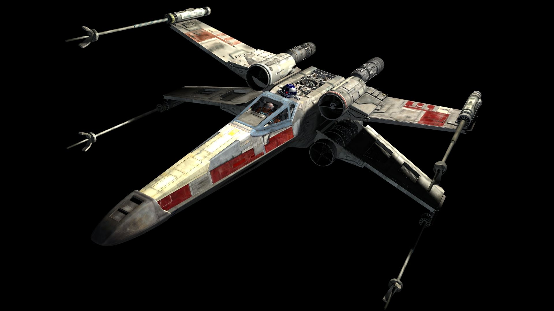
I think that my Z-95 Headhunter is fairly accurate to the actual model. However a problem I had when designing the model is that there are different variations and representations on how the Z95 should look when researching for images on search engines such as Google. For example 
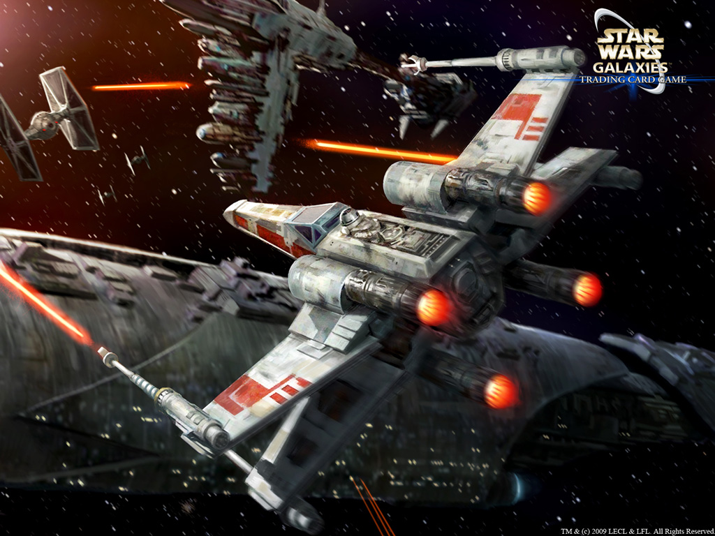
this image gives the impression that the ship has a wide base whilst this image gave the impression it was thinner. This made it difficult to create an accurate representation of how the Z-95 Headhunter should truly look.

The biggest improvement I could make to my Z-95 Headhunter is improving the textures. Whilst I did apply textures to the ship, they were simple metal textures I created using the pattern tool in Photoshop. Although I did use some colour in the textures, I did not recreate individual bits of details which are in the actual ship. This is due to my lack of skills in Photoshop.

X-Wing

The X-Wing was the second model I created in Maya. One problem which occurred when designing this model was the angles of the wings. Due to the way the wings are rotated in the actual X-Wing model, I found it difficult to get a symmetrical positioning of the wings on each side. I was not able to use the Mirror Geometry tool in this case. I did partially overcome this by using the method where I would put the scale in a negative value to flip the wing. Although this helped, some wings were still not rotated properly and it took some time messing around with the scale and rotation of the wing till I was able to accurately position the wing. This made it difficult to perfectly position the wings in precise positions and rotations.

I do believe my X-Wing is accurate however there are some issues with the positioning of the four engines and four wings which could definitely use some improvement, however I did find it difficult to position without objects going through each other. Tools such as the align tool were not helpful in this case.

The biggest improvement I could have made to my X-Wing is improving the textures. Again like I mentioned with my Z-95 Headhunter, my Photoshop skills are not great so I was not able to add too much detail to my X-Wing. I feel like bump mapping may have helped greatly in improving the accuracy of my X-Wing. Another improvement I could make is the positioning of the engines and wings, however difficulties as mentioned earlier made this harder to accomplish.
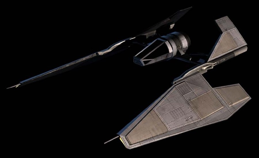
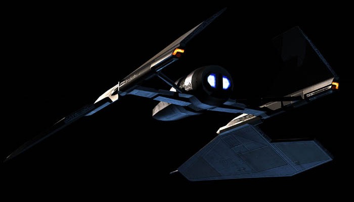
Sith Fighter

The Sith Fighter was the final model I made in Maya. Since this was my last ship made, I rarely ran into any issues since most of my mistakes and issues made were experienced in my first two models and therefore I was able to avoid these issues whilst creating this model. I do realize however that I have some issues with the accuracy of the model. Comparing to other images of the Sith fighter, the top half of the wing should be larger, however due to the shape of the ship, I was unable to fix this in time for submission. There are also some other minor shape details I could have added to the bends of the wings however due to time and efficiency in polygon count, I decided to leave these details out.

Another downside as mentioned in the previous two other models is that the textures could be improved greatly. Although I did assign a texture to almost all of the objects in the scene, the textures were not great quality and do much match the actual Sith fighter with great accuracy. With better skills in Photoshop, I may have been able to get better results.

Saturday 1 November 2014

Texturing my sith fighter

I began to texture my Sithfighter model. I used Adobe Photoshop CS2 to design my textures as it seemed to be the most suitable software due to important features such as layers, patterns and selection tools such as the magnetic lasso tool which made it easier to select the UV Maps I created.

Before creating a new UV, I created a new material on the object. Typically I used the "Lambert" material but on my other ships such as the X-Wing I used the "Blinn" material for a better metal effect. I found that the default UV maps from the different objects used in my ship were most of the time; messy, unorganised and confusing. To get around this issue I used the "Planar Mapping" tool under the "Create UV's" menu in order to make the designing of the textures a lot easier. Below are the following steps I took to do this:

1. Select the faces on the object which I wanted to map.

2. Under the "Create UV's" menu, click "Planar Mapping."

3. Move, rotate and scale the Planar Projection into the correct positioning to get the best UV projection possible. Repeat for all the faces needed for texturing.

4. Once all faces are mapped, in the UV texture editor, take a UV snapshot. Below are the settings I mostly used. The size I used typically depended on how many different faces were in a certain object. Objects which had a high amount of faces would typically be a higher size due to more space needed for texturing.

I often used the image format: TIFF or PNG. This is because these two formats have minimal quality loss compared to other image formats.
5. Once the snapshot was saved I would import it into Photoshop and begin editing. I would often seperate each group of faces into seperate layers by using the magnetic lasso tool inside Photoshop to easily select the faded lines generated by the snapshot.

I would then begin each texture by using the fill bucket to give each group of faces a basic colour. Afterwards I would use the pattern overlay tool to give each group of faces the appropriate texture. This would often be a metal texture provided in Photoshop.


When each design is finished in Photoshop, each file would be saved as a TIFF as this format is very raw and gives the best quality possible when imported back into Maya.

The finished project:


Tuesday 21 October 2014

The Sith fighter

Today I began working on my next Star Wars ship model, The Sith fighter. The images I used to aid in creating this model were:

 The Base/Cockpit

I began by creating the base/cockpit of the model which did not consist of any advanced techniques. The front of the model is a cylinder with reduced axis sub divisions which can be applied through the attribute editor. I then proceeded to use the move tool to bring the front of the cylinder forward and then used the scale tool to make the cylinder become progressively thinner.

 The engine of the ship also consists of another cylinder. To manipulate its shape to create thin and thick parts of the shape, I used the extrude tool. The steps I took were:

1. Select all the faces on the back of the cylinder.
2. Use the "extrude face" tool to extrude the faces.
3. Use the scale tool and reduce the size of the faces selected.
4. Extrude the faces again (skip if making progressively thinner/thicker) and use the move tool to stretch them backwards.
5. Repeat when needed.


The Wings

I began creating the wing by creating the connections between the base and the wing. The first part consisted of two cubes. The first cube included the use of the "Difference" tool which can be found under the Mesh drop down bar in the Boolean tools. This allowed me to manipulate the cube by putting another cube inside the shape where I wanted it to be cut as shown in the screenshot below.

After I had completed one side of the wings I used the group feature (CTRL + G) and named the group "right wing." I then duplicated the right wing group and reversed the scale of the Z axis from 1 to -1. This gave me an issue where all the faces began inside out (appeared black) which I was able to fix by reversing the normals. (Normals > Reverse.)

The result was this:

 Now that I finished designing my Sith fighter, I made sure that all the groups I created during the creation of the model were named and organised properly by opening the Outliner from the Window drop down. I also began preparing the texture all three of the star wars models I had designed.


Wednesday 15 October 2014

Working on the X Wing ship

Today I began working on my second Star Wars ship, the X-Wing. Compared to my previous ship, the Z-95 HeadHunter, there were a lot more 3D images of the ship I could use to give me a good accurate guidance for modelling this ship. The images I am using for guidance are:


I began by creating a cylinder and reducing its subdivision axis to 6 to give it the same shape body as the X-Wing.
To create the nose of the X-Wing I selected the top and bottom edges of the front of the cylinder and used the scale tool to close them in together. I also selected the edges on the sides and used the move tool to make the cylinder more pointy as seen below.
To create the rest of the body, I selected the faces from the back of the cylinder and used the extrude face tool to extend the body and used the scale tool so that it gradually became bigger and thicker. To change the falloff point I used the soft select tool and modified the fallout radius as well as the fallout curve.

I created the cockpit by using the edge loop tool to create more edges. By using the move tool on the newly created edges, I was able to create the "slope" on top of the base to give the shape of a cockpit. 

To create the laser cannon of the ship, I created a cylinder. To manipulate the shape of it, I used the edge loop tool as well as the extrude tool to create the thin and thick parts of the shape. I found this was much more effective than what I did with the Z95 HeadHunter which was just creating multiple cylinders and resizing them.
To create the curled "C" shape of the laser cannon, I used the bend tool to bend a cube into a "C" shape. To do this I first had to create a cube and set its height subdivisions to 6. I then changed to the animation menus. From there I went to Create Deformers > Nonlinear > Bend. In the attribute editor, I had to modify the curvature till I got the result I wanted.

After I added some detail onto the wings, I ran into some issues with the three other wings after duplicating them and getting them into the correct rotation after being placed in the different positions. 

One way I found which helped me overcome my problem when flipping the wing is to set its scale to a negative value. The problem I encountered with this however is that all the faces could be flipped inside out which would cause the wing to turn black as shown in the image below.

To overcome this I found that if you highlight all the faces of the wing and go to Normals > Reverse in the menu, it flipped the faces so they faced the right way.
After creating the four engines and adding in some extra details, I had completed modelling the ship. 


Sunday 12 October 2014

Z95 Headhunter continued and finished

The Cockpit

I began working on the Z95 Headhunter's cockpit. I did this by adding a couple of edge loops to the base of the ship. I then rotated two of the new edges created both diagonally to make the cockpit look thin like the actual Z95. I then raised the back edge to give the "ramped" look of the cockpit.

The rest of the ship

As you can see in the below screenshot, I used the edge loop tool multiple times. This was so that I could get the smoothest curve when I increased the height of the Cowling (see Z9 headhunter schematics in previous blog post.) Although this was costly on polygon count, I wanted my ship to look as accurate as possible.


Saturday 11 October 2014

Designing the Z-95 Headhunter continued...

In my last blog post I explained how I created the base, wings and laser cannon.

Today I worked on creating the engines and manipulating the base of the ship to create a cockpit.

The Engines

My engine consisted of multiple pipes overlapping each other. Although I found this used more polygons than just using one pipe and using the edge loop tool to manipulate the shape of the pipe , I found this did not look as accurate as using multiple pipes. The amount of extra polygons was also not too expensive than using the edge loop tool.

Creating the main pipe
Creating more pipes
The front of the engine
 For the front of the engine, I used the scale tool to widen a cube. I then sub divided width by 7. I then selected the top middle face and used the move tool to increase its height.

To create the curved pipe as you can see in the second screenshot of the engine, I created a pipe as normal and then selected the front faces and used the scale tool so it became progressively smaller.


I then extruded the faces on the opposite side.

With the engine finished, I proceeded to copy and paste the engine into three other locations.

Engine now completed